


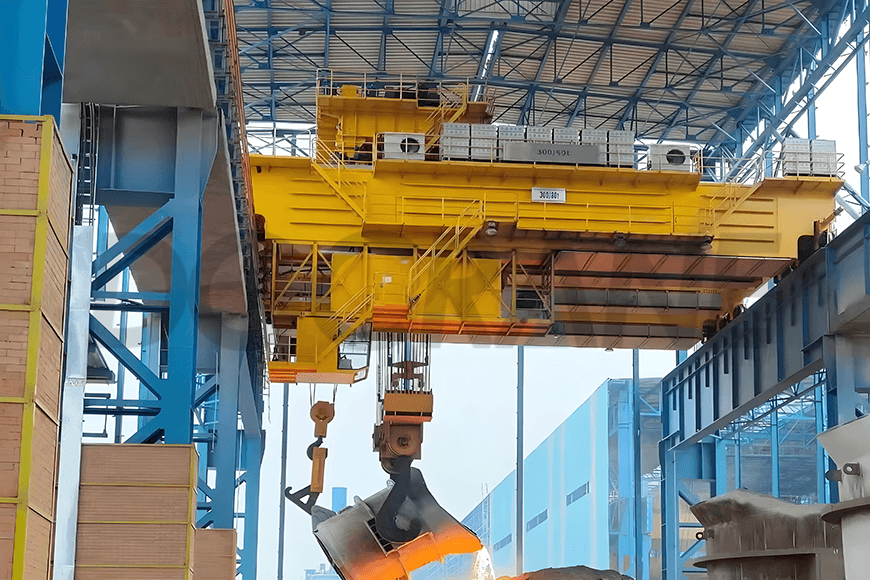
YZ Ladle Handling Cranes for Foundry: Safe Solutions for Lifting Molten Metal
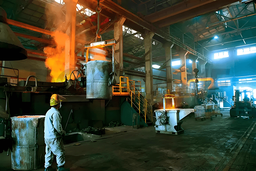
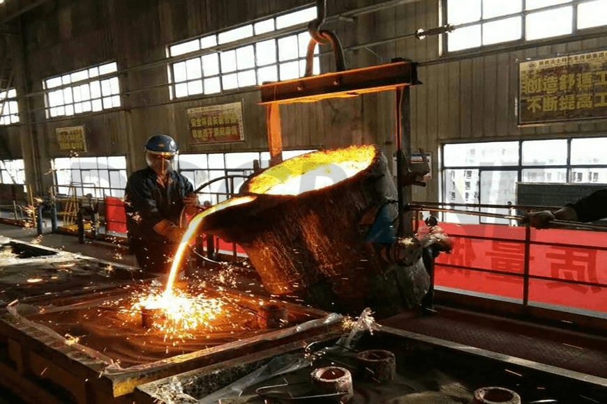
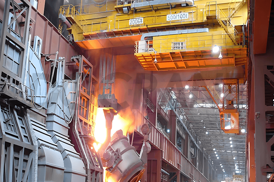
Ladle handling cranes are mainly used for transferring molten iron from the converter charging bay to the converter, transporting molten steel to the refining furnace in the refining bay, or lifting and moving molten steel to the ladle turret on the continuous casting machine in the steel receiving bay. They are one of the key pieces of equipment in the steelmaking continuous casting process.
Ladle handling cranes are critical equipment in the steelmaking continuous casting process, primarily used for lifting and transferring liquid steel ladles.


Applications
Ladle handling cranes are mainly used in the steelmaking continuous casting process to pour molten iron from the additive bay of the converter into the converter, transport molten steel from the refining bay to the refining furnace, or transfer molten steel from the steel receiving bay to the ladle turret of the continuous casting machine. Ladle handling cranes operate in harsh environments with high temperatures and heavy dust, requiring a high-duty class and stringent safety standards for the equipment.
Technical Features
- The primary purpose of this equipment is to lift and transfer molten liquid metals. Ladle handling cranes are of a high-duty class, with extremely stringent safety requirements.
- The bottom of the main girder is equipped with a heat insulation layer to reduce the adverse effects of high-temperature radiation on the girder's strength and prevent potential safety hazards.
- The operator’s cabin and electrical room are both fully insulated, with cooling equipment (mostly industrial air conditioning) installed inside.
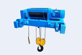
- The wire ropes used are high-temperature-resistant steel-core wire ropes (either metal strand core or metal rope core).
- The pulley sets on the hook group or lifting attachments and the fixed pulley sets on the trolley are fully enclosed to effectively extend the lifespan of the components.
- All motors have H-class insulation and IP54 protection rating.
- The main hoisting motor is equipped with an overspeed switch, ensuring the safety brake on the drum end can quickly engage in case of failure.
- Each end of the high-speed shaft of the hoisting reducer is equipped with two brakes, with a safety disc brake on one end of the drum.
- The hoisting drum is a welded drum, and most pulleys are rolled pulleys.
- When the main hoisting mechanism uses two drive systems, if one motor or electrical control system fails, the other drive system should ensure that one work cycle can be completed with the rated load.
Specification
For more detailed specifications, please refer to DGCRANE’s catalog of ladle handling cranes.
Cases
50/10t Double Girder Double Rail Ladle Handling Crane Installed in the Slag Bay of a Steelmaking Plant
The 50/10t ladle handling crane is installed in the slag bay of a steelmaking plant, operating outdoors in an environment characterized by high altitudes, heavy dust, high temperatures, and high humidity.
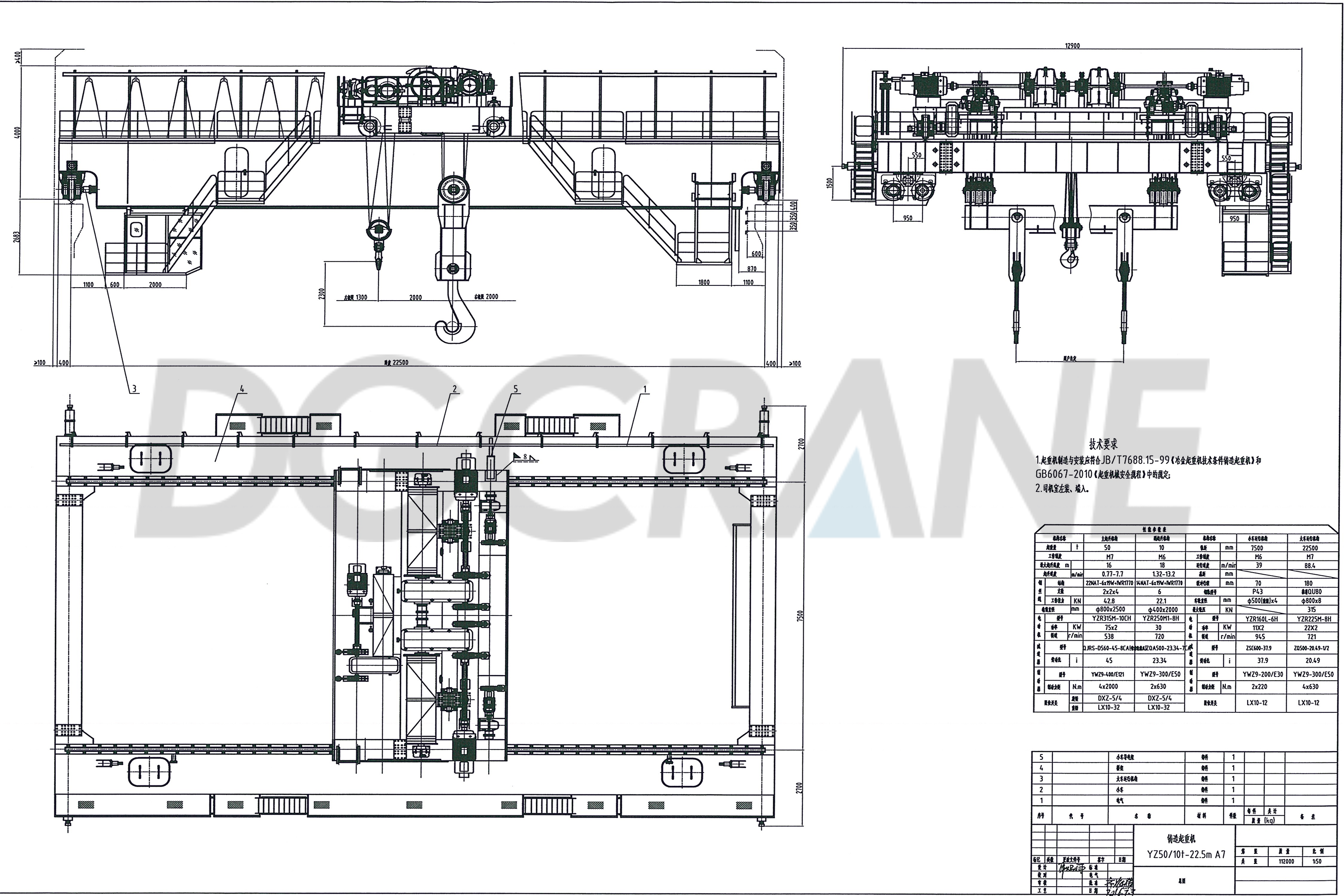
Technical Features
- The ladle handling crane’s main girder adopts a double-girder, single-trolley structure, with both the main and auxiliary hoisting mechanisms arranged on the same trolley. The main girder is a fully offset wide box girder.
- The lifting beam attachment adopts a fixed gantry hook type, and a heat radiation shield is installed under the lower flange plate of the gantry hook.
- A heat radiation shield is also installed under the lower flange plate of the main girder.
- Ladle handling crane's buffer system uses rubber buffers.
- The operator’s cabin and busbar are installed on the same side, with the busbar fitted with a rain cover.
- The operator’s cabin is fully enclosed with a double-layer structure.
- The main hoisting mechanism uses two motors and two reducers, ensuring that if one motor or electrical control system fails, the other drive system can safely complete a work cycle with the rated load.
- Each drive system in the main hoisting mechanism has two independently working brakes.
- The main hoisting mechanism uses four steel wire ropes. If one rope fails, the remaining ropes ensure that the load can still be safely placed in a secure position with the rated load.
- All wheels are made of forged alloy steel, and the pulleys are rolled pulleys.
- The wire ropes are suitable for high-temperature environments and have a sufficient safety factor.
- The movable pulley cover on the gantry hook is fully enclosed.
- The power distribution cabinet is installed in the electrical room within the enclosed box girder, and the resistor is installed above the main girder.
- The power supply to the trolley is provided by a drag cable system, using heat-resistant cables.
- The crane is equipped with zero-position protection, limit switches, overload protection, etc.
- The hoisting mechanism has overspeed protection switches.
- The main and auxiliary hoisting mechanisms use mechanical limit switches, with upper and lower limit protection. The main hoisting mechanism also has weight hammer limit control in addition to the mechanical limit.
- Control lines in the cabinet use flame-retardant FVL wire, and all bridge wiring has heat protection.
- The main busbar is a rigid busbar, and the operator's cabin is located on the same side as the busbar.
- The electrical room on the main girder is equipped with two high-temperature air conditioners, and the operator’s cabin is equipped with one heating and cooling air conditioner.
70/20t Double Girder Double Rail Ladle Handling Overhead Crane – Slag Bay Crane Retrofit Project in the Steelmaking Workshop of a Stainless Steel Company
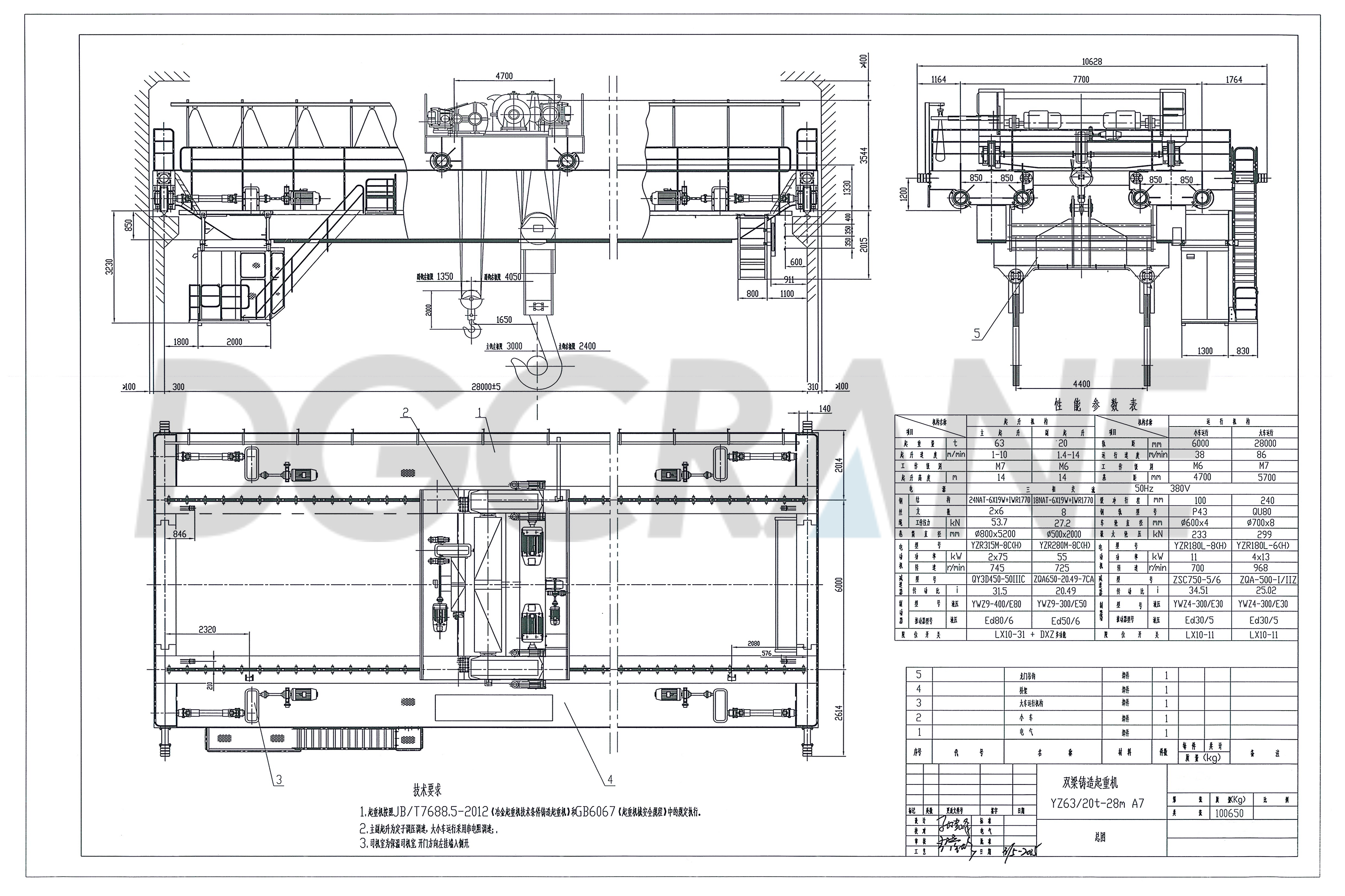
Features
- The motors are specially designed for metallurgical cranes, with an insulation class of H. In addition to meeting heating and overload requirements, the hoisting motor is designed for the special working conditions of ladle cranes, allowing the other motor to operate briefly and complete a work cycle when one motor fails.
- The reducer is a dedicated ladle crane reducer with ratchet and hardened gears and a welded casing.
- The hoisting mechanism is equipped with an electronic scale with alarm, digital display, and relay output functions. The display is installed in the operator's cabin to prevent overload operation.
- The hoisting mechanism uses dual limit protection with rotating and weight hammer-type limit switches.
- The wire ropes are made of high-quality, line-contact, alternating-lay wire ropes.
- The main hoisting attachment is a gantry hook type. A heat radiation shield is installed under the lifting beam to reduce the impact of external radiation heat on the attachment. The auxiliary hoisting hook is a forged single hook, with a freely rotating hook head.
- The movable pulley block (with individual lubrication for each pulley) has a fully enclosed protective cover with adequate dust exit holes at the bottom.
- The wheels are standard double-flange cylindrical wheels, made from forged or rolled steel (material: 42CrMo), with a tread hardness of HB300-380 after medium-frequency quenching. The crane’s buffer system uses spring buffers.
- The operator’s cabin is welded from steel plates and shaped steel, with double-layer insulation at the bottom, and air conditioning is installed inside.
Safety Protection Devices
- Undervoltage Protection: In the distribution protection panel, a contactor circuit is used as the undervoltage protection device. All control panels of each mechanism are equipped with Undervoltage protection devices, which automatically cut off the circuit power when the power supply is interrupted.
- Zero Position Protection: Before the crane starts or after the power is restored following an Undervoltage situation, all controllers must be returned to the zero position before the motors of each mechanism can start.
- Hoisting Limit Protection: The main and auxiliary hoisting mechanisms both use rotary limit switches, ensuring that the power to the hoisting mechanism is automatically cut off when the hook reaches its upper or lower limit. When the deceleration limit switch is triggered, the lifting and lowering speed is limited to within 10% of the rated speed, though the mechanism can still operate at full speed in reverse. The weight hammer limit serves as the ultimate protection for hoisting. When the weight hammer limit is triggered, the main contactor cuts off power, shutting down the entire crane.
- Bridge Travel Limit Protection: The traveling mechanism of the crane is equipped with collision prevention devices at both ends, with adjustable power cut-off, alarm, and deceleration functions (2m–15m).
- Trolley Travel Limit Protection: The trolley mechanism has deceleration and terminal limit switches at both ends, serving as travel limit protection.
- Emergency Power Cut-Off Protection: An emergency switch is installed in the control circuit of the crane. In case of an accident, the switch can cut off the control circuit power to ensure safe crane operation.
- Safety Switch for Railings and Doors: Safety switches are installed on the crane entry doors and the bridge ladder doors. If any safety switch is opened, the main relay for bridge travel will be automatically disconnected, prohibiting bridge travel and preventing accidents caused by unauthorized entry onto the bridge platform. Proximity switches are used for safety control.
- Over-Speed Protection for Hoisting Mechanisms: Both the main and auxiliary hoisting mechanisms use stator voltage regulation and speed control. An overspeed switch is installed on the motor shaft, which triggers if the lowering speed exceeds the set limit. This cuts off the motor power and engages the brake, preventing the hook from slipping due to system failure.
For more detailed information on the safety protection devices of foundry cranes, please click here to read our dedicated article, 5 Critical Safety Protection Devices for Ladle Cranes: Enhancing Safety and Reliability in Steelmaking
Other Types of Ladle Handling Cranes
The overall structure of YZ ladle handling cranes can be categorized into double-girder double-rail, four-girder four-rail, and four-girder six-rail types. The double-girder double-rail and four-girder four-rail types are generally used for medium and large-capacity ladle handling cranes, while the four-girder six-rail double-trolley type is generally used for ultra-large capacity ladle cranes.
At DGCRANE, our ladle handling cranes are engineered with safety and precision as top priorities, providing dependable performance in challenging foundry environments. Designed to manage molten metal with care, these cranes incorporate advanced safety features to help protect both operators and equipment.
Whether you're seeking increased durability, enhanced control, or reliable operation, DGCRANE offers professional solutions tailored to meet the unique demands of your steel production. Rely on our expertise to support the efficiency and safety of your operations.


