- INDUSTRIES
-
EQUIPMENT
-
Overhead Cranes
-

Single Girder Overhead Crane
-

Double Girder Overhead Crane
-

Underslung Cranes
-

Workstation Overhead Cranes
-

Low Headroom Overhead Cranes
-

Grab Bucket Overhead Crane
-

Electromagnetic Overhead Cranes with Lifting Magnet
-

Electromagnetic Overhead Cranes with Magnet Beam
-

Manual Overhead Cranes
-

Double Trolley Overhead Cranes
-

LDP Single Girder Overhead Cranes
-
- Eot Cranes
- Gantry Cranes
- Jib Cranes
- FEM Standard Crane & Hoist
- Hoist & Winch Trolley
- Light Cranes
- Explosion Proof Cranes and Hoists
-
Special Cranes
-

35-65t Clamp Overhead Crane
-

Boat Hoists
-

Boat Jib Crane
-

Yacht Davit Crane
-

Rail Mounted Container Gantry Crane
-

Cleanroom Overhead Cranes
-

YZ Ladle Handling Cranes
-

LDY Metallurgical Single Girder Crane
-

Charging Cranes for Steel Production
-

Insulated Overhead Cranes
-

Gantry Crane for Subway and Metro Construction
-

Forging Crane
-

Quenching Overhead Crane
-

Baking Multifunctional Crane
-
- Port Cranes
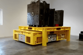
- Electric Transfer Carts
-
Overhead Cranes
-
CRANE PARTS
- Crane Wheel Range
- Crane Spreader
- Crane Drives
-
Crane Electrical Equipment
-

Overload Limiter
-

Crane Cabin
-

Crane Power Supply System
-

Explosion Proof Crane Radio Remote Controls
-

Joystick Type Crane Radio Remote Controls
-

Pushbutton Type Crane Wireless Remote Controls
-

Single-pole Insulated Conductor Rails
-

Enclosed Conductor Rails
-

Seamless Conductor Rails
-

Copperhead Conductor Rails
-

Overhead Crane Cables
-
- Other Cranes Parts
\
- ABOUT US
- CONTACT US


60/50t Structural Principle and Characteristics of Steel Ingot Clamp Crane
The steel ingot clamp crane is an indispensable piece of lifting equipment on the steel ingot rolling line. It is mainly responsible for loading the cold steel ingot into the heating furnace, removing the heated steel ingot, and putting it into the steel ingot turning device. In addition, the clamp is also used for steel ingot stacking, slag scraping and cleaning at the bottom of the homogenizing furnace. The 50 t auxiliary hook is used for the maintenance of heating furnace equipment and the lifting of other production items. 60/50 t steel ingot clamp crane is used for production. Its large lifting weight, advanced technology, high safety and reliability can improve the production efficiency of the entire steel ingot rolling line.
1. Work characteristics and main technical parameters
The steel ingot clamp crane works according to a certain process on the steel ingot rolling line, and its workflow can be divided into 4 stages:
• Hoist the steel ingot from the car transporting the steel ingot to the steel ingot storage area, and cooperate with the grinding personnel to perform the ingot turning operation;
• Lift the polished steel ingots in the storage area to the homogenizing furnace and place them against the furnace wall for furnace installation;
• The steel ingots that have been heated according to the process are hoisted out of the homogenizing furnace to the steel ingot receiving device or directly hoisted to the rolling mill roller;
• Use 50 t auxiliary hooks to overhaul and maintain ground equipment such as heating pits, capping machines and furnace covers.60/50t steel ingot clamp pliers.
60/50 Steel Ingot Clamp Crane table of main technical parameters.
| Project | Technical parameters | |
| Rated lifting weight/t | Main lifting mechanism | 60 |
| Secondary lifting mechanism | 50 | |
| Crane span/m | 36 | |
| Crane work level | A 7 | |
| Lifting height/m |
Main lifting mechanism | 10 |
| Secondary lifting mechanism | 24 | |
| Lifting speed(m/min) | Main lifting mechanism | 1~10 |
| Secondary lifting mechanism | 0.53~5.3 | |
| Running speed/(m/min) | Trolley | 4~40 |
| Hoist | 4~40 | |
| Working level of each component | Main lifting mechanism、Trolley | M 7 |
| Hoist Run, rotate, open and close | M 6 | |
| Secondary lifting mechanism | M 4 | |
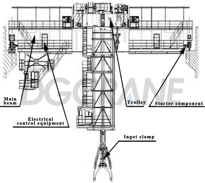
Composition and structural characteristics of crane
The 60/50 t steel ingot clamp crane is installed in the main rolling, which can work safely and reliably in the harsh environment of high temperature and roasting.The whole machine is composed of a cart axle, a cart frame, a steel ingot clamp, a cart operating mechanism, and electrical control equipment, which is a double-beam, double-rail, single-cart layout type.
Structural characteristics of crane beam frame
The bridge frame is the main carrying part, and the bridge frame is composed of the main beam and the end beam.The main beam adopts a wide flange partial rail box beam, which has good vertical and horizontal stiffness, and the main force material adopts Q345B. In order to avoid fatigue damage to the main beam caused by concentrated wheel pressure, T-shaped steel is used under the track, which greatly improves the life of the main beam. In order to ensure assembly accuracy, the end beam is also a box beam structure.The connection between the main beam and the end beam is made of high-strength bolts.
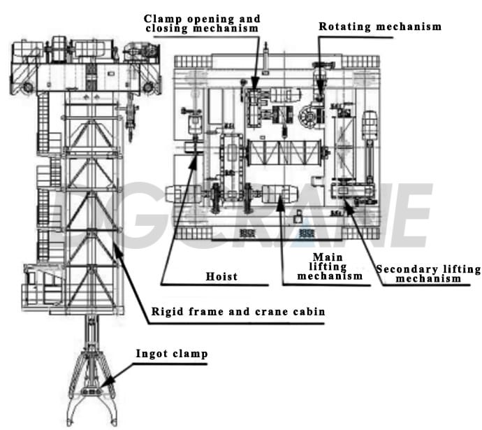
Structural characteristics of the trolley
The trolley frame is made of steel plate welded with section steel. The trolley platform is equipped with a main and auxiliary lifting mechanism, an opening and closing mechanism, a trolley operating mechanism, and a rotating mechanism.The rigid frame is bolted under the trolley frame, and the lower cab is installed on the platform at the bottom of the frame.
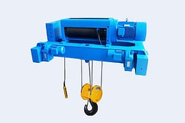
Lifting mechanism
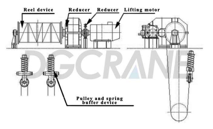
In order to make full use of the space on the trolley rack and make the layout of each mechanism compact, the reels of the main and auxiliary lifting mechanisms are arranged vertically.The main lifting mechanism is dragged by dual motors, and the reel is driven by brakes and reducers to rotate, so that the wire rope rises or falls, driving the upper beam and the square column supported on the thrust bearing in the center of the beam together with the steel ingot clamp to rise or fall.The main lifting mechanism has the following characteristics:
1. Adopt the form of dual motor and single reducer.The input of the reducer is a dual motor and the output is a single reel output. The layout is tight and the maintenance is convenient.
2. A spring is used as a buffer device above the fixed pulley.When the crane is clamping the red steel ingot in the homogenizing furnace, there is a short-term ingot extraction process due to the bonding of the dissolved slag at the bottom of the furnace. To this end, the spring device can effectively reduce the impact of the spreader on the trolley at this time.
3. The two wire ropes used for lifting the ingot clamp are fixed to the double part at both ends of the reel of the main lifting mechanism.The lifting wire rope bypasses the fixed pulley block under the buffer spring of the trolley frame and the moving pulley block in the upper beam, which is fixed to the reel.One end of the wire rope used for the opening and closing mechanism is fixed to the single part in the middle of the lifting reel, and the other end is fixed to the reel of the opening and closing mechanism after it bypasses the moving pulley block of the clamp opening and closing mechanism.This can ensure the synchronization of the opening and closing mechanism and the lifting mechanism.
4. The lifting height of the main lifting mechanism must be satisfied: when the opening of the ingot clamp is the largest, the clamp can still clamp out the ingot that is flat on the bottom of the furnace.
Clamp opening and closing mechanism
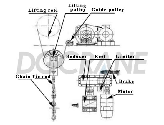
The function of the clamp opening and closing mechanism is:Drive the opening and closing of the clamp legs of the clamp to adapt to steel ingots of different widths and sizes. The opening and closing of the clamp are achieved by the action of the opening and closing mechanism driving the lifting pulley. When the clamp clamp frame does not move, the opening and closing mechanism drives the lifting pulley and tie rod through the motor, reducer, reel, and wire rope. The tie rod and chain then drive the hinge contact of the clamp rod to lift and lower, so that the roller on the clamp rod rolls in the figure-eight chute of the clamp frame, forcing the clamp rod to open or close. The opening and closing wire rope is fixed to the opening and closing reel and the lifting reel at both ends through the guide pulley and the lifting pulley, respectively, to ensure that the opening and closing mechanism is not affected by the lifting of the clamp.The lifting of the opening and closing wire rope is opened by the clamp, and the lowering of the opening and closing wire rope is closed by the clamp.
Clamp rotating mechanism
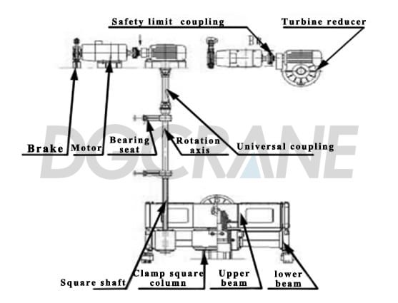
It is used to drive the clamp to rotate to achieve the purpose of placing the ingot in place and scraping the slag.The driving part of the rotating mechanism is arranged on the trolley frame, and the driving part extends down into the frame below the frame.
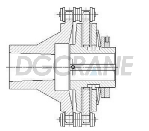
1. The driving part. The driving part of the rotating mechanism is installed on the small rack platform. It consists of a motor, a reducer (in the form of a worm gear), a chain friction safety coupling, and a brake. The output shaft of the reducer leads to the inner hole of the lower beam pinion gear through the coupling, universal shaft and square shaft. The driving part of the rotating mechanism of the clamp has the characteristics: when the two clamps are hoisting the steel ingot to rotate, due to the large resistance, the chain friction safety coupling is set in the transmission chain to effectively protect the mechanism from damage due to overload, as shown in Figure 6; The position of the reducer shaft and the lower square shaft is far away, and the universal coupling connection between the two can avoid affecting the normal transmission of the rotating mechanism due to insufficient installation accuracy.
2. Transmission power.The transmission part of the rotating mechanism consists of three parts: the upper and lower beams and the clamps. The upper beam is a welded structure, and a moving pulley block is installed on it. The trapezoidal nut and thrust bearing seat supporting the square column stigma of the clamp are installed between the two pulley blocks. It is responsible for the lifting of the entire clamp (including steel ingots), the square column, and the lower beam. The lower beam is a special reducer body, which is equipped with a two-stage reducer gear pair. The drive mechanism drives the square shaft to rotate, the square shaft then drives the small and medium gears of the lower beam to rotate, and then drives the large gears to rotate through the intermediate gears; the large gears (the inside of the large gears is a square hole) rotate; and the square column drives the clamp to rotate.
In order to ensure that the upper and lower beams have good guiding performance when sliding in the frame along the guide rails on the frame, guide grooves are provided at both ends of the upper and lower beams. When the main beam rises, the upper beam and the square column rise together. After rising to a certain height, the upper flange of the square column contacts the bottom of the lower beam, and then supports the lower beam as it rises.
Ingot clamp
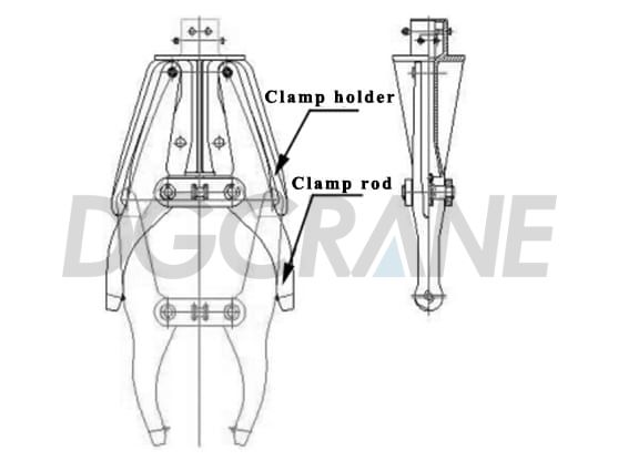
The steel ingot clamp is a special picking device used to clamp cold and hot steel ingots. It consists of three parts: a clamp frame, two clamp rods, and a square column connected to the clamp frame. Due to the different sizes and positions of the steel ingots being hoisted, and the hot and cold temperatures vary greatly, the position of the steel ingots to be clamped needs to be changed frequently. In order to ensure that the clamp maintains sufficient clamping force in all states, the eight-shaped chute guide rail curve of the clamp frame is composed of two arc curves with a radius of 10 m left and right. In order to make the clamp device work reliably, the clamping coefficient K≥1 is often taken into account in the design 1.8~2.0 (K is the ratio of the horizontal clamping force of the clamp tip to the lifting force).
Rigid frame and crane cabin
The upper part of the rigid frame is connected to the trolley rack by high-strength bolts, and the lower cab is installed on the lower platform. The frame is welded from steel plate and section steel. The rigid frame is provided with guide rails on the east and west sides, which can guide the rise and fall of the upper and lower beams, and at the same time can resist the circular force during rotation.The cab is installed at the bottom of the rigid frame. In order to enable the driver to clearly observe the clamping of the steel ingot when operating, the cab is set close to the front and rear of the clamp. Since drivers often work above the heating furnace, the temperature is very high and the working conditions are bad, so special heat insulation panels are set up around the bottom of the cab and the bottom of the frame, refractory bricks are laid on the platform, and high-temperature heating and cooling air conditioners are set up in the driver’s room.The observation glass of the cab adopts high temperature resistant glass that protects against infrared radiation.
Crane trolley operating mechanism
The operating mechanism of the crane trolley is a four-corner drive, and each group of drives consists of a motor, a reducer, a brake, a universal shaft, etc. A horizontal wheel set is set on the end beam of the non-sliding contact line, which can make the crane have good steering performance when running at high speed.The operating mechanism of the cart adopts frequency conversion and speed regulation, which can obtain a speed adjustment of 4~40 m/min, stable starting and braking, and accurate positioning.
Characteristics of electrical control equipment
The electrical control system of the 60/50 t steel ingot clamp crane is mainly composed of the main and auxiliary lifting mechanism, the operating mechanism of the large and small trolley, the rotating mechanism, and the control system of the opening and closing mechanism. In addition, there are auxiliary systems such as power distribution, lighting, overload limiters, and integrated monitoring systems. The main features of the crane’s electronic control system are as follows:
1. Control of the main lifting mechanism.The main lifting mechanism adopts an AC stator voltage regulating and speed regulating system, with a speed-regulating ratio of 1:10; The main lifting mechanism is driven by two motors and controlled by a set of speed regulating devices. When one motor fails, another motor can be used to complete a working cycle to solve the emergency response. A rotary switch is installed on the short axis of the tail of the reel, which rotates synchronously with the reel, and the rising and falling limits of the lifting mechanism are controlled by collecting the parameters of the number of revolutions of the reel.A hammer limit switch is provided on the trolley. When the ingot clamp rises to the upper limit, the rope supporting the hammer loses tension, the limit switch is reset, the power supply is cut off, and the mechanism stops.The shaft end of the motor is equipped with an overspeed switch to detect the operating speed of the motor and realize the overspeed protection of the motor.
2. Control of trolley operation and trolley operation mechanisms. The operation mechanism of the large and small trolley adopts a frequency conversion speed control system, which is driven by a frequency conversion motor, and the speed control ratio is 1:10; the operation mechanism of the trolley is controlled by a set of frequency converters and one motor is driven; the operation mechanism of the large car is driven by four electric motors, and two frequency converters are used to control the motors in the same beam. When one set of motors fails, it is dragged by another set of motors.For cranes and trolleys, operating stroke limit switches are installed in each operating direction, and when the limit position specified by the design is reached, it is touched by a safety ruler in the same direction to cut off the power supply in the forward direction.
3. Institutional communication system.The auxiliary lifting mechanism, rotating mechanism, and opening and closing mechanism adopt a series resistance speed regulation system; the system includes a wireless intercom system between the crane cabin and the ground, a boarding contact device, and a driver-to-ground broadcasting system.
4. Integrated monitoring system.The integrated monitoring system adopts automatic fault monitoring and protection.The comprehensive control adopts a programmable controller; the crane is equipped with an alarm light box, which can display faults such as overvoltage, undervoltage, overcurrent, motor overcurrent, and overheating.
5. Other auxiliary systems.Other auxiliary systems include an under-bridge lighting system, an automatic lubrication system, a maintenance socket, an air conditioning control system, and a real-time monitoring system.The real-time monitoring system consists of two sets of high-temperature cameras, a set of industrial monitors, an information processing system, and an electrical control system.The industrial monitor is installed in the driver’s room at the lower end of the main beam. The operator can use the image on the monitor to determine the status of the clamp and the crane, so as to perform accurate operations.
3.Conclusion
The 60/50 t steel ingot clamp crane has been innovated in the structural layout. The electronic control system adopts the mature and advanced control mode of the crane. In terms of safety protection, more consideration is given to the needs of high temperatures and harsh working conditions. Its application in the steel ingot rolling line production line not only improves the operating environment, reduces the labor intensity of operators, and ensures the reliability and safety of steel ingot rolling. It also greatly improves the production efficiency of the extra-thick plate rolling line, which provides a guarantee for the safe and efficient production of extra-thick plates.
DGCRANE focusing on exports for 15 years, if you need 60/50 t steel ingot clamp cranes, we can provide you with the best quality products and services.

Zora Zhao
Expert in Overhead Crane/Gantry Crane/Jib Crane/Crane Parts Solutions
With 10+ years of experience in the Crane Overseas Export Industry, helped 10,000+ customers with their pre-sales questions and concerns, if you have any related needs, please feel free to contact me!