-
INDUSTRIES
-

Precast Concrete Plant
-

Steel Industry
-

Paper Industry
-

Waste to Energy and Biomass Industry
-

Power Industry
-

Overhead Cranes for Automotive Production: Smart Solutions for Enhanced Efficiency
-

Port Machines Industry
-

Manufacturing Industry
-

Different Types of Container Cranes, Shipyard Cranes, Cargo Cranes Used in Port, Harbor and Quay
-

Overhead Cranes for Timber Lifting: Efficient and Safe Wood Handling
-

Overhead Cranes for the Aviation Industry: Streamlining Aircraft Assembly, Maintenance, and Repair
-

Overhead Cranes for Food and Beverages: Ideal for improving productivity and food safety
-
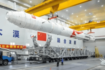
Overhead Cranes for Aerospace Industry: Key Role in Efficient Rocket Manufacturing and Launch
-
-
EQUIPMENT
-
Overhead Cranes
-

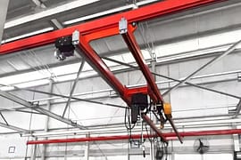
Single Girder Overhead Crane
-

Double Girder Overhead Crane
-

Underslung Cranes
-

Workstation Overhead Cranes
-

Low Headroom Overhead Cranes
-

Grab Bucket Overhead Crane
-

Electromagnetic Overhead Cranes with Lifting Magnet
-

Electromagnetic Overhead Cranes with Magnet Beam
-

Manual Overhead Cranes
-

Double Trolley Overhead Cranes
-

LDP Single Girder Overhead Cranes
-
- Eot Cranes
- Gantry Cranes
- Jib Cranes
- FEM Standard Crane & Hoist
- Hoist & Winch Trolley
-
Light Cranes
-

Portable Mobile Gantry Cranes
-

Adjustable Gantry Cranes
-

Aluminum Gantry Crane
-
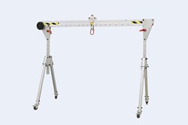
Foldable Aluminum Gantry Crane
-

Monorail Overhead Cranes
-

Workstation Jib Cranes
-

Electric Hoists
-
Workstation Overhead Cranes
-
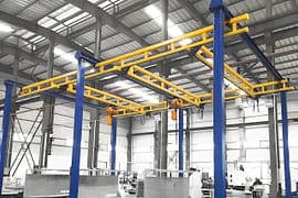
Freestanding Workstation Bridge Crane
-
Ceiling Mounted Workstation Bridge Crane
-

Manual Portable Gantry Crane
-

Multi-point Suspension Cranes
-
- Explosion Proof Cranes and Hoists
-
Special Cranes
-

35-65t Clamp Overhead Crane
-

Boat Hoists
-

Boat Jib Crane
-

Yacht Davit Crane
-

Rail Mounted Container Gantry Crane
-

Cleanroom Overhead Cranes
-

YZ Ladle Handling Cranes
-

LDY Metallurgical Single Girder Crane
-
Charging Cranes for Steel Production
-

Insulated Overhead Cranes
-

Gantry Crane for Subway and Metro Construction
-
Forging Crane
-

Quenching Overhead Crane
-

Baking Multifunctional Crane
-
- Port Cranes
- Electric Transfer Carts
-
Overhead Cranes
-
CRANE PARTS
- Crane Wheel Range
- Crane Spreader
- Crane Drives
-
Crane Electrical Equipment
-

Overload Limiter
-

Crane Cabin
-

Crane Power Supply System
-

Explosion Proof Crane Radio Remote Controls
-
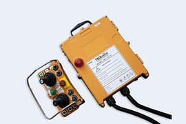
Joystick Type Crane Radio Remote Controls
-
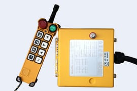
Pushbutton Type Crane Wireless Remote Controls
-

Single-pole Insulated Conductor Rails
-

Enclosed Conductor Rails
-

Seamless Conductor Rails
-

Copperhead Conductor Rails
-

Overhead Crane Cables
-
- Other Cranes Parts
\
- ABOUT US
- CONTACT US


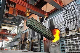
5 Critical Safety Protection Devices for Ladle Cranes: Enhancing Safety and Reliability in Steelmaking
Table of Contents
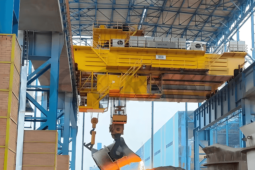
A ladle crane is a critical piece of equipment in the continuous steel casting and rolling process, specifically used for hoisting molten metal. If a major accident occurs, it can lead to severe consequences, including casualties and equipment damage. The safety protection devices of the crane are essential equipment to ensure its inherent safety, acting as an important barrier to prevent operator errors and to safeguard both personnel and machinery.
Whether the safety protection devices are intact and complete, whether maintenance and management are timely and effective, and whether they function sensitively and reliably play a significant role in the normal operation of the crane. These devices are indispensable components of the crane. Due to the specific nature of ladle cranes handling hot molten metal, their safety requirements differ from those of ordinary cranes.
Load-Limiting Devices
The purpose of the overload protection device is to prevent the crane from overloading, which could lead to damage to the mechanism, structure, or cause accidents. The overload protection devices used in ladle cranes mainly include electronic scales and overload limiters.
When a load limiter is installed on the hoisting mechanism, it is typically positioned at the drum-bearing seat. If an electronic scale is installed on the main hoisting mechanism, it also functions as an overload protection device, with its sensors usually mounted beneath the fixed pulley shaft.
When the actual load exceeds 95% of the rated load, the load limiter sends an alarm signal. If the actual load falls between 100% and 110% of the rated load, the load limiter cuts off the hoisting power, allowing only downward movement of the hoisted material, but preventing it from being lifted further. The electronic scale is set in the same manner.
Travel-Limiting Devices
These mainly include hoisting travel limit switches, running travel limit switches, photoelectric anti-collision devices, buffers, and end stops.
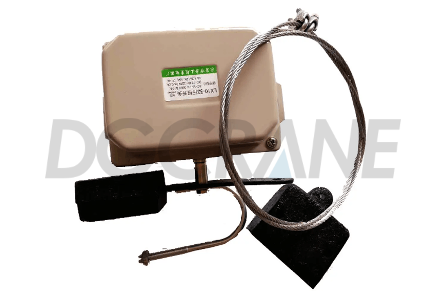
Hoisting travel limit switch
The hoisting travel switch consists of a rotary limit switch and a weighted hammer limit switch, with two sets of switches of different structures used together to ensure safe and reliable operation. When the lifting device reaches the designed upper limit position, both switches can automatically cut off the hoisting power. When the device descends to the designed lower limit position, the rotary limit switch automatically cuts off the descending power (this is set when the hoisting height exceeds 20 meters). It also ensures that when the lifting device descends to the lower limit position, the wire rope remains wound around the drum with no less than the two turns specified by the design.
After the motor power for upward or downward movement is cut off, the power for movement in the opposite direction remains, allowing the mechanism to operate in reverse. The rotary switch is installed on the short shaft at the end of the drum and rotates synchronously with the drum, collecting the rotation count to control the hoisting limit for ascent and descent.
The weighted hammer switch is installed on the trolley frame, with the hammer itself mounted on the pulley block support bracket of the gantry, and the hammer sleeve fixed to the hoisting wire rope. When the gantry reaches the upper limit, the supporting rope loses tension, resetting the limit switch and cutting off the power to stop the mechanism.
Running travel limit switch
The limit switch and bumper are set on the main beam. The crane and its main and auxiliary trolleys are equipped with running travel limit switches in each direction. When the crane reaches the designed limit position, the safety rod triggers the switch in the same direction, cutting off the power for forward movement. In cases of high-speed operation (e.g., greater than 100 m/min) or where strict stopping position requirements exist, two-stage running travel limit switches are installed as needed. The first stage sends a deceleration signal to slow the crane down, while the second stage automatically cuts off the power and stops the crane.

Photoelectric anti-collision device
Some cranes are equipped with a photoelectric anti-collision device to prevent collisions between two cranes running on the same track. The basic principle is that when two cranes approach a certain safe distance, the light emitted by crane A’s projector is received by crane B’s receiver. Through the photoelectric tube, an electrical signal is generated. After waveform shaping and amplification, the relay is activated, and the buzzer sounds an alarm, automatically cutting off the running mechanism’s power. Both cranes must be equipped with a set of such devices for mutual protection.
Buffers and end stops
The running mechanisms of both the crane and trolley are equipped with buffers. Buffers are designed to absorb the energy of moving mechanisms and reduce the impact. The bumpers and end stops on the track should be firm and reliable. The design of end stops must effectively prevent the crane from derailing.
Other Safety Devices
Interlock protection devices
The doors leading to the ladle crane and those providing access from the operator’s cabin to the bridge platform are equipped with interlock switches. When the doors are opened, the power to all mechanisms is cut off.
Rail sweepers
Rail sweepers are installed at the front of the wheels on both the crane and the trolleys. The clearance between the bottom of the sweeper plate and the top of the rail is set to 10 mm, and they are used to clear debris that may obstruct operation on the rails. Warning signs are placed alongside the track, prohibiting material from being piled nearby.
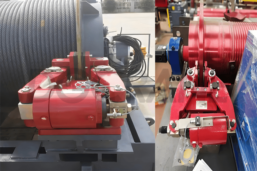
Emergency brake
The emergency brake is a safety protection device that is controlled by a detection system composed of a high-reliability overspeed switch and an encoder. In case of failure in the hoisting mechanism transmission chain—such as overspeeding of the drum, drum asynchrony, emergency button activation, or sudden power failure—the emergency brake engages to effectively and reliably stop the drum, ensuring the crane's safety.
The emergency brake is mounted at the end of the drum. Compared with conventional brakes, it generates much greater braking torque, sufficient to independently overcome the torque generated by the full load on the hoisting mechanism’s drum. The main hoisting mechanism is equipped with two sets of driving devices, and when no rigid connection exists on the output shaft or when there is only one driving device, an emergency brake must be installed on the wire rope drum.
Protective Devices
Protective covers
Pulley covers are installed to prevent the wire rope from slipping out of the groove. Protective heat insulation plates are installed beneath the gantry lifting device to protect the wire rope from direct radiation heat and prevent molten steel from splashing onto the wire rope. Protective covers (or rails) are installed to shield exposed, potentially dangerous moving parts, such as couplings and transmission shafts, during operation. Warning signs are attached to the protective covers.
Electric shock prevention
When the ladle crane's operator’s cabin is located on the side of the crane’s sliding contact line, electric shock hazards exist. In the relevant sections, protective nets are installed between the crane's ladder and walkway and the sliding contact line for isolation, and warning signs are posted on the net.
Fall protection
Support plates are installed below both ends of the drum to prevent it from falling in case of drum removal or shaft breakage. Safe and reliable maintenance cages or platforms are set up at the ends of the bridge to provide a standing area for personnel to perform crane maintenance. Any exposed connecting bolts after installation are spot-welded to prevent loosening and falling.
Safety Information and Alarm Devices
These mainly include amplitude indicators, levels, wind speed and wind grade alarm devices, reverse alarms, dangerous voltage alarms, electrical interlock protection devices, bells or signal devices, and safety signs.
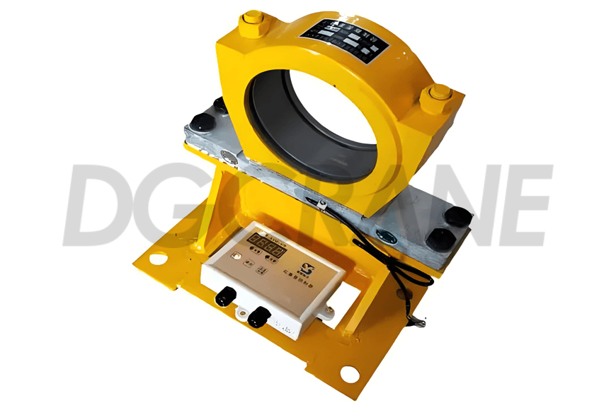
Overspeed switch
The Safety Regulations for Lifting Appliances stipulate that “important hoisting mechanisms and unbalanced luffing mechanisms, where overspeeding would cause danger, should be equipped with overspeed switches. The set value of the overspeed switch depends on the performance of the control system and the rated lowering speed, typically set between 1.25 to 1.4 times the rated speed.” The hoisting mechanism of ladle cranes is generally equipped with an overspeed switch, often integrated with the hoisting motor. If there is no installation space at the rear of the motor, the switch is connected to the reducer’s high-speed shaft.
Height indicator
The height indicator is primarily used in the hoisting mechanism to measure and display the distance between the crane hook and the ground. The instrument’s control output contacts are optional, and it can provide remote secondary interfaces. The height sensor usually uses an encoder, and it can be combined with a limit switch. The height indicator is typically installed at the drum’s end.
Speed detection system
Due to the special nature of casting operations, some components require speed detection systems. In case of any abnormalities, the detection system identifies the fault point, and the PLC simultaneously sends a corresponding braking signal to the emergency brake, preventing accidents.
For casting cranes using hoisting mechanisms with planetary reducers, a typical speed detection system is applied. The system consists of the following components:
- Incremental encoders installed on both motor shafts
- Incremental encoders were installed at both drum ends
- Overspeed switches were installed at both drum ends
The incremental encoders on the high-speed and low-speed shafts output a constant number of pulses per revolution, corresponding to the motor and drum speeds. These encoders form a detection and control system with the PLC. The encoder’s pulse count is input into the PLC for calculation, and by comparing the pulses on the high-speed and low-speed shafts, the system verifies whether the transmission chain of the hoisting mechanism is normal. The overspeed switches monitor whether the drum’s rotational speed exceeds the set safe limit. If abnormal operating conditions occur, the system detects the fault and takes action.

Zora Zhao
Expert in Overhead Crane/Gantry Crane/Jib Crane/Crane Parts Solutions
With 10+ years of experience in the Crane Overseas Export Industry, helped 10,000+ customers with their pre-sales questions and concerns, if you have any related needs, please feel free to contact me!
WhatsApp: +86 189 3735 0200
Email: zorazhao@dgcrane.com
Contact Details
DGCRANE is committed to providing the professional Overhead crane products and relavent service. Exported to Over 100 Countries, 5000+ Customers Choose Us, Worth to be Trusted.
Get In Touch
Fill out your details and someone from our sales team will get back to you within 24 hours!